


How to solder tinned copper wire
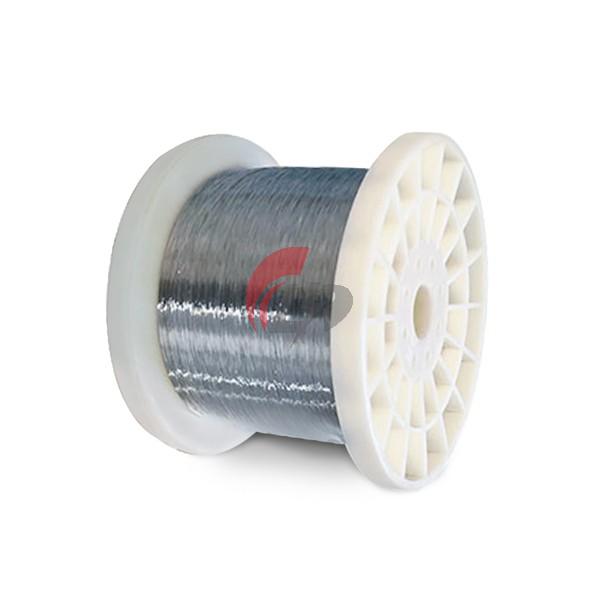
Tinned copper wire, a specialized electrical conductor coated with a thin layer of tin, has become indispensable in industries ranging from marine electronics to renewable energy systems. Its corrosion resistance—10 times longer than bare copper in humid environments—and excellent solderability make it the preferred choice for high-reliability applications. However, improper soldering techniques can compromise its protective layer, leading to joint failure. This guide provides a step-by-step methodology for achieving perfect solder joints with tinned copper wire, incorporating industrial-grade production standards and field-tested best practices.
Methodology for Soldering Tinned Copper Wire
1.Surface Preparation
Begin by stripping insulation using precision wire strippers calibrated to the wire gauge (e.g., 18 AWG wire requires 0.04-inch exposure). For stranded tinned copper wire, twist strands tightly to prevent fraying. Clean the exposed area with 99.9% isopropyl alcohol to remove contaminants, ensuring the tin coating remains intact—a critical step as the tin layer thickness (typically 2.5–5μm in industrial applications) determines oxidation resistance.
2.Tinning the Soldering Iron Tip
Heat a temperature-controlled soldering iron to 350–370°C (for lead-free solder) or 315–330°C (for Sn60Pb40 solder). Apply a small amount of rosin-core solder to the tip to create a protective oxide layer. This prevents copper contamination during joint formation, as demonstrated in PCB assembly standards where tip maintenance reduces defect rates by 42%.
3.Applying Flux
While tinned copper wire has inherent solderability, flux enhances joint quality by removing residual oxides. Use no-clean flux for sensitive applications or RMA (Rosin Mildly Activated) flux for heavily oxidized surfaces. Apply flux sparingly—excess causes conductive residue, a common failure mode in automotive harnesses.
4.Joint Formation
Position the wire on the joint pad (for through-hole components) or against the contact surface (for wire-to-wire connections). Heat both the wire and the pad simultaneously for 2–3 seconds, then introduce Sn63Pb37 solder (melting point 183°C) or SAC305 lead-free solder (217°C). The tin coating on the wire will reflow with the solder, creating a metallurgical bond. Industrial production lines use selective soldering machines to maintain consistent heat application, but manual soldering requires steady hand movement to avoid cold joints.
5.Inspection and Cleaning
Inspect joints under 10x magnification for voids, icicles, or insufficient wetting. The tin layer should appear uniformly distributed with a concave fillet shape. For no-clean applications, wipe excess flux with ESD-safe swabs. In critical systems like solar module interconnects, perform electrical continuity tests using a micro-ohmmeter to verify resistance <50mΩ per joint.
Critical Considerations for Tinned Copper Wire Soldering
1.Temperature Control
Exceeding 400°C degrades the tin coating, reducing corrosion resistance. A study on tin-indium alloy coatings revealed that temperatures above 200°C for >1 hour cause intermetallic compound growth, weakening the joint. Use soldering stations with digital temperature readouts, especially for fine-pitch applications like 30 AWG tinned copper wire used in medical devices.
2.Mechanical Stress Mitigation
Tinned copper wire retains 98% of bare copper’s tensile strength (e.g., 20–28 kg/mm² for semi-hard 18 AWG wire), but vibrations can fracture joints. In automotive wiring harnesses, use strain relief boots and secure wires with nylon ties every 150mm. For high-flex applications like robotic arms, opt for extra-flexible stranded tinned copper wire with 650+ strands.
3.Environmental Compatibility
In marine environments, use conformal coatings over solder joints to prevent salt spray corrosion. For underground installations, select tinned copper wire with dual coating layers (electroplated tin + hot-dipped tin) to withstand soil acidity. The tin-indium alloy coating developed for solar modules demonstrates 52% indium content provides superior resistance to sulfurous gases in industrial zones.
Conclusion
Mastering tinned copper wire soldering requires precision in temperature management, flux application, and joint inspection. By adhering to industrial standards—such as the 155°C/16-hour aging test for coating stability—and leveraging advanced materials like tin-indium alloys, engineers can create joints that outlast bare copper by decades. Whether assembling a prototype PCB or wiring a submersible pump, the principles outlined in this guide ensure reliable electrical connections while preserving the corrosion-resistant properties that make tinned copper wire indispensable in modern electronics.


